

Simple Circuits Curriculum
Section 5: Background Information
The Basics of Series and Parallel Circuits
Series and parallel circuits are some of the most commonly taught concepts in units on electrical circuits. Understanding the differences between them is not always easy.
In a series circuit, two or more bulbs are connected in a line, or a series. The wire from the negative contact of the battery goes to a bulb, and a wire from that bulb goes to another bulb and so on, until the wire coming from the last bulb in the series goes back to the positive contact of the battery. When current in the circuit flows, it passes through each of the bulbs directly. In the case of a series circuit with two bulbs, each bulb is directly connected to one node of the battery, but not the other node; the pathway from the bulb to the second node has to go through the other bulb. Two bulbs provide more resistance in the circuit than one, so given a standard voltage, the current flowing in a two-bulb series circuit is less than the current flowing in a single-bulb circuit.
In a parallel circuit, two or more bulbs are both connected directly to the same battery. So typically more than one wire leaves the negative contact of the battery1 and each wire is connected to a bulb. The wires coming from the bulbs typically each attach back to the positive contact of the battery. Parallel circuits characteristically have branches or splits in the circuit, and are sometimes difficult to identify, because the bulbs may seem to be connected to each other in a series-like way with wires.
In order to decide if a bulb is in a parallel circuit, see if you can trace a line from each node of the battery directly to each bulb without passing through another bulb. If so, the circuit is a parallel circuit. The resistance of a bulb is a physical property and doesn't change regardless of what type of circuit it is in. In a two-bulb parallel circuit, each bulb has the same individual resistance as it did in the series circuit. However, the resistance of the entire parallel circuit is less than the resistance of a series circuit because the current has multiple pathways through a parallel circuit. It can be difficult for students to think about resistance in the individual bulbs and in the entire circuit at the same time—in fact, it can be hard to understand why the two are different at all.
A "cars on the highway" analogy may help explain the distinction: think of a wide highway narrowing to a one-lane bridge to cross a river. Now imagine that in order to get rid of traffic jams, the highway department builds another one-lane bridge over the river. The "resistance" (in this case analogous to the width), of both bridges stays the same, but the amount of "current" or traffic that can cross the river has increased, so the overall "resistance" of the entire system has decreased.2
In a parallel circuit, the brightness of the bulbs does not change with the addition of more bulbs, but if you added many parallel circuits, eventually all of the bulbs would dim down as you approached the capacity of the battery.
Some Configurations of Series and Parallel Circuits
| Series Circuit (Bulbs in series) |
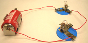 |
| Parallel Circuit (Bulbs in parallel) |
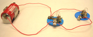 |
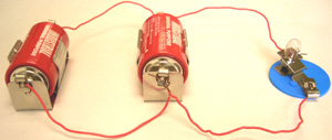
| Series Circuit (Batteries in series) |
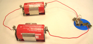 |
| Parallel Circuit (Batteries in parallel) |
 |
This lesson also introduces what happens when batteries are in series or in parallel. Arranging batteries in series increases the amount of voltage so bulbs will appear brighter. Arranging the batteries in parallel results in the same amount of voltage, but there is more (battery) material available so that the batteries are able to last longer and will be able to maintain their voltage (differential) when there is a higher flow of current. The bulbs in the circuit will be the same brightness as they were before adding additional batteries.
Students' Intuitive Models of Parallel and Series Circuits
Teachers commonly ask students to hook up series and parallel circuits and to see what happens. However, this experimentation does not necessarily lead students to formulate new models of the circuit. In fact, they typically use whatever model made sense to them before (Double Linear, Cyclic Sequential, and so on) and apply it to reasoning about circuits in parallel or in series. Their underlying models can be so strong that sometimes students actually perceive what they expect to happen and are unable to see what really happens in their experiments. So while you might think that one set of ideas is being conveyed, your students may be extending their misconceptions into new territory. What do these misconceptions sound like? When student hold Linear or Cyclic Sequential Models, they typically think that the bulb closest to the negative terminal of the battery lights before bulbs "further along" (from the perspective of this model) in the circuit. They also think that bulbs "further along" will be less bright because "some of the current will be used up." Another common belief is that only the bulb closest to the negative terminal will light. They often extend this reasoning to parallel circuits and use distance from the negative terminal to reason about how bulbs in a parallel circuit will light as well.
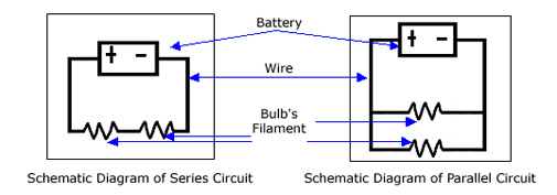
Note to Teacher: There are a variety of representations to illustrate circuits: conceptual models, schematic diagrams, and illustrations, for example. This curriculum focuses on conceptual models. The schematic diagrams below are the type that electricians and scientists use to show the configuration of a circuit. We include these examples to share with students. However, these schematic diagrams do not offer insight into why or how the circuit works. Therefore, the focus of the module is on conceptual models instead of schematic diagrams.
Applying the Cyclic Simultaneous Model to Parallel and Series Circuits
Even if students have learned about the Cyclic Simultaneous Model, they will not necessarily apply it on their own. Therefore, it is important to get students to model what is going on so that you can see their responses, and to talk explicitly with students about how to apply the Cyclic Simultaneous Model. Without this opportunity, students will learn what happens in the particular circuits that they test. However, they will not have the conceptual tools to reason about any variations on these circuits.
The Cyclic Simultaneous Model is a good intermediate model for explaining what happens in series and parallel circuits. It forces us to look at the circuit as a system instead of as isolated parts. It serves as a good bridge between the Cyclic Sequential Model and the Electrical Potential Model in Lesson 8. Because the amount of resistance in a circuit varies with the number of light bulbs, and the amount of voltage varies with the number of batteries in the circuit, parallel and series circuits can help students learn about Ohm's Law and the relationship between voltage, resistance, and current.